Automated Lamp With Arduino
Hey folks. In this post we are going to see how we can build an automated lamp with Arduino and a bluetooth module. So let's get started!
Introduction
Arduino is a hobbyist's right arm. This small piece of wonder comes bundled with just the right tools for any small-to-medium sized hobby project and all that for a reasonable price too. Now we are going to use the Arduino to automate the working of an LED lamp. Here, by "automate" , I do mean "automate" and so it should not require any human input once it is up and running. However, it also should not irrevocably interfere in any way with a human's lifestyle. Therefore we first have to form a principle of working. For this project, I have chosen the following principles:
- The LED should light up when the amount of ambient light is low. It also should be powered by rechargeable batteries and not the mains so it can work even if there is a power outage.
- The LED should be capable of being turned off manually with convenience. For that, I have chosen to go with bluetooth to turn it on or off.
Now that we have the principles in place, let's get down to building it.
Things we need for this project (Apparatus)
We require the following things for this project.
Note: You can use dot board to minify the circuit but it is advisable to use a bread board for realizing the circuit first. Also, I have used Arduino UNO in this project and so the instructions that follow are for Arduino UNO exclusively but just about any of the Arduinos should do.
- Bread board
- Jumper Wires
- HC-05 Bluetooth module
- LED light
- Resistors (220 ohm)
- LDR
- Arduino UNO R3 (usually comes with a cable)
- USB Charger ( preferable output of 5V 1A )
Once we have gathered all the supplies we can begin assembling the circuit.
The Circuit
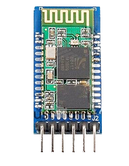
The HC-05 bluetooth module looks like this:

If it does, then look on the back side bottom edge (the ends of the pins). If you find a "5V" written somewhere there then just go ahead and connect the corresponding pins to the Arduino inputs, i.e, 5V to the 5V, GND to the GND, Rx to Rx and Tx to Tx. However, as I have read in some online tutorials, if you find a "Vcc" written there, then the connections are as follows:
- Vcc of HC-05 to 5V of Arduino
- GND of HC-05 to GND of Arduino
- Rx of HC-05 to Tx of Arduino
- Tx of HC-05 to Rx of Arduino
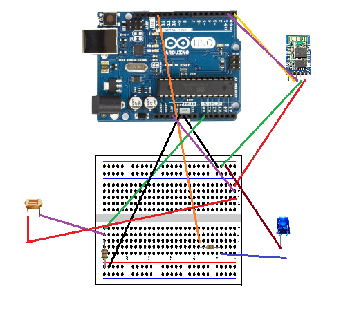
Since we do have to connect the other components to the Arduino pins too, the circuit could be built like this:

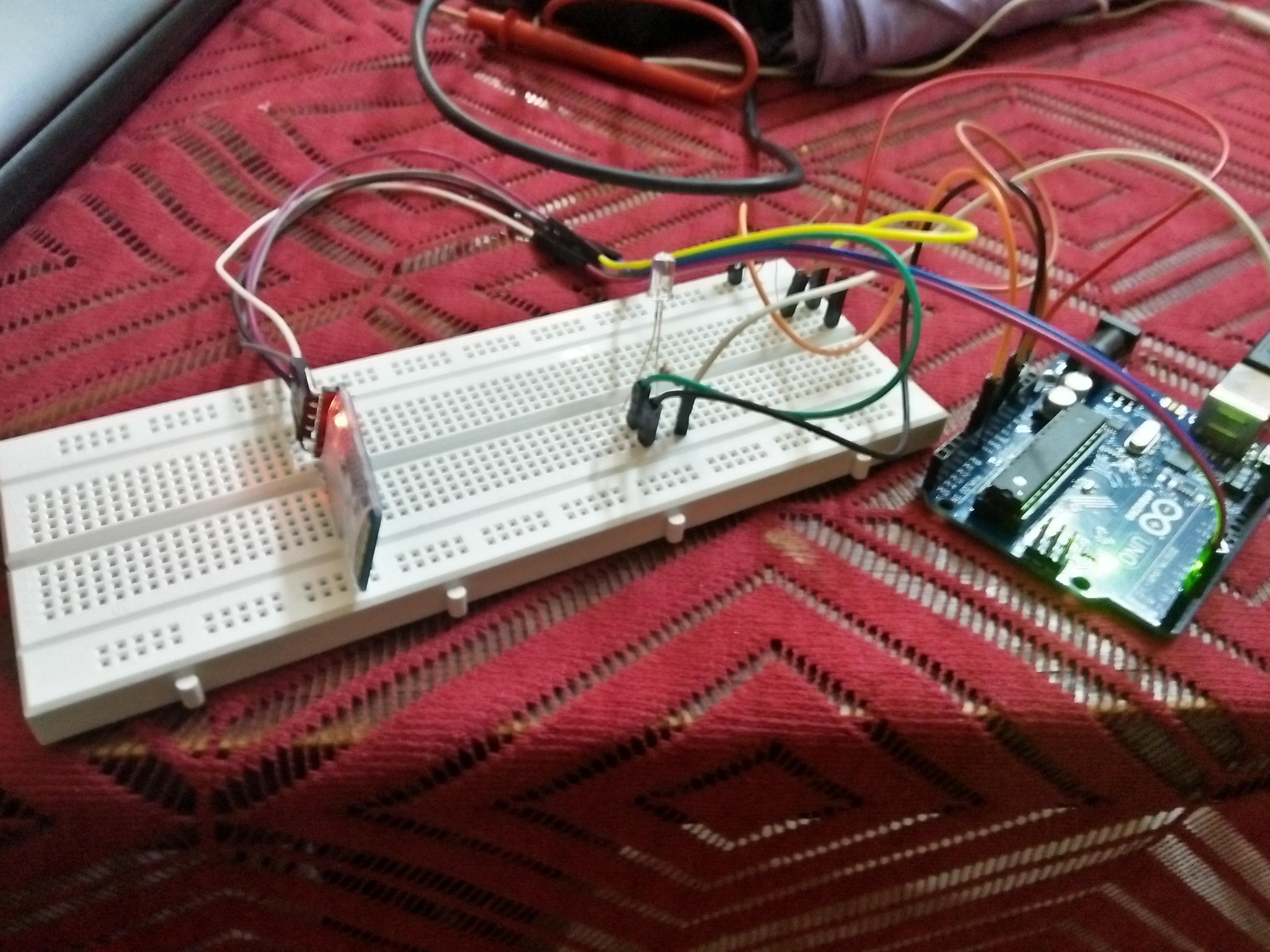
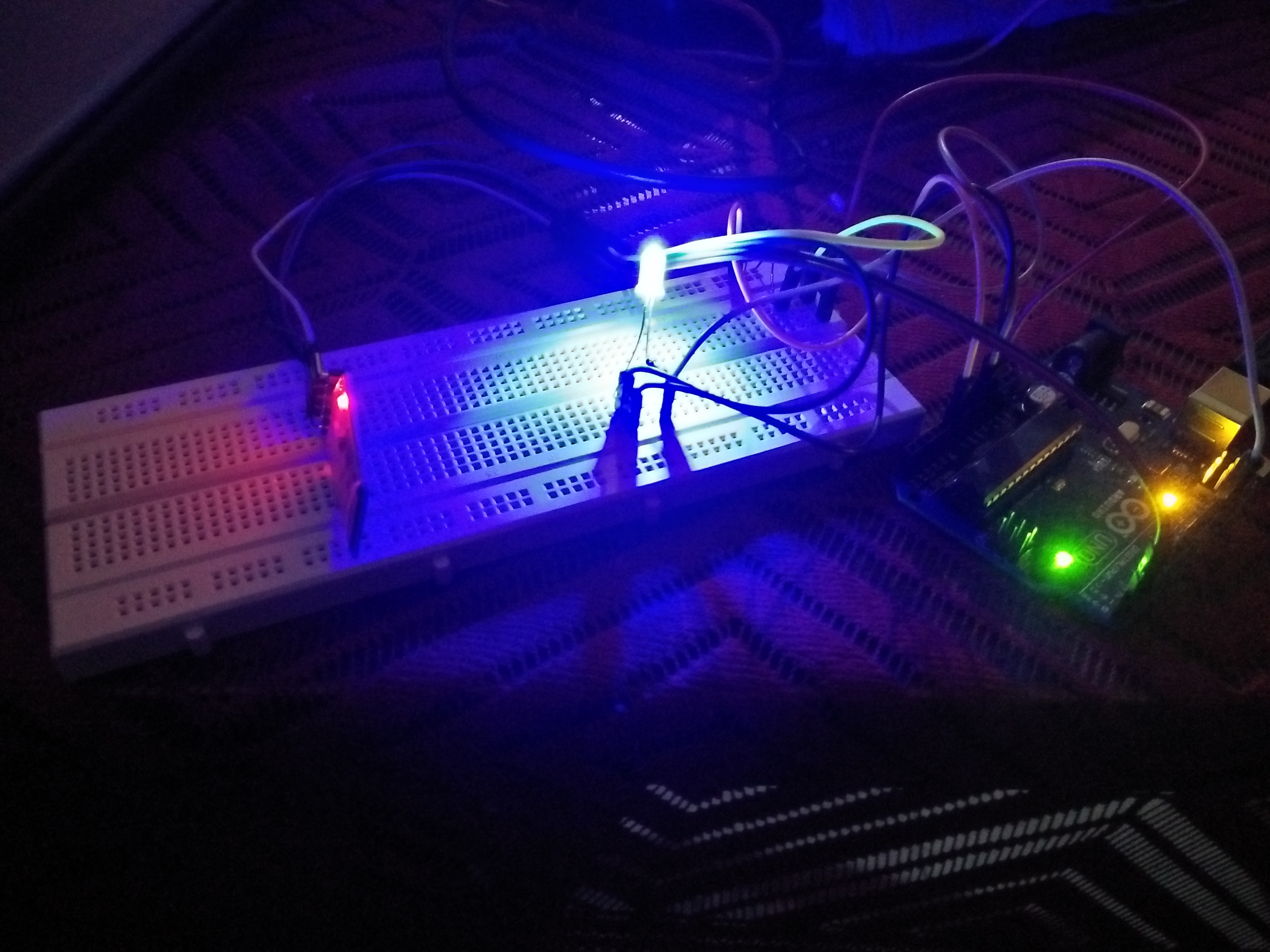
The component on the left of the breadboard in the diagram is the LDR and on the right is the LED. Note that you have to try to keep the LED and the LDR as far apart as possible. This is because the LDR (Light Dependent Resistor) roughly tells us about the amount of light it can sense around itself. If the light is low, the LED lights up. But if the LED is too close to the LDR, it will keep lighting up momentarily and turning off or just keep flickering as the LDR values will fluctuate. Also, try to turn the LDR head away from the direction of the LED. For a more visual demo of the circuit see below:

Program the Arduino
The next step is to program the Arduino according to our needs. We need to capture the data from the LDR and the bluetooth module simultaneously. If the user instructed the arduino to keep the light off, then it stays off no matter what. Else, if the environmental light is low, turn the LED On. The program looks like this:
#include <SoftwareSerial.h>
#define LDRPin A0 SoftwareSerial btSerial(1,0);
int LDRValue = 0;
int key = 1;
char data = 0;
void setup(){
    btSerial.begin(9600);
    pinMode(13,OUTPUT);
}

void loop(){
    if(btSerial.available()){
        data = btSerial.read();
        key = (int)data - 48;
    }
    LDRValue = analogRead(LDRPin);
    if(LDRValue < 3 && key > 0){
        digitalWrite(13,HIGH);
    } else{
        digitalWrite(13,LOW);
    }
}
In writing the above code, I have assumed that you have arranged the circuit as was given in the diagram above. If not, the code may vary. After uploading the code, the HC-05 should blink twice or thrice as should the Arduino UNO. If you get an error saying that something like "avrdude: stk500_recv(): programmer is not responding" or "avrdude: stk500_getsync() attempt 1 of 10: not in sync: resp=0x0d", then do not worry. Just disconnect the HC-05 pins and reconnect them and then retry uploading the code. It should compile and upload. After that, we are ready to fire it up.
Turn off your lights, the LED should glow.

Turn the lights back On and the LED should switch off automatically.
Working with the Bluetooth
Now that we are through with this, we have to manually turn the device on or off. For that, you can download any Bluetooth Terminal App on your phone. I am using Android and I have downloaded this app.
Once you have the app, open the app and change to ASCII mode. Also, make sure to turn off returning the carriage return ( \r ) and the new line ( \n ) characters at the end of the serial data. On the prescribed app above, I do it by long pressing the Send ASCII button to bring up the options and then turning the two checkboxes off in the Select ending for Sent data section and choosing ASCII in Select Sent data type section. Now we are good to go.
Try switching off the light, and the LED turns on. Now send 0 to the bluetooth. The LED turns off even in the dark. Send 1 again and the LED turns back on. A general question would be, "When is the extra control helpful ?" To answer that, first we have to take into consideration that this was only a prototype. The real lamp would be powered by DC batteries. The whole point of this lamp, as we can see, is to save energy. Now suppose you want to leave for work. You would turn all light of your house off and only then leave. Now since the lamp is powered by the battery, unless turned manually off it will use up the charge in the battery to a futile cause. This is why we would need the extra bit of control.
Possible Extensions
We have reached the end of this project. Now let us broadly explore how we can extend this concept to achieve better results. Some possible extension could be as follows:
- Automated Home Lighting - With a few PIR sensors ( can roughly detect human presence ) we can extend the same circuit to controlling lights of entire rooms. Switch them on only when human movement is detected.
- Thermoregulator - Instead of using an LDR, we can use a Thermometer and instead of LED, a heating element. By sensing the current temperature using the Thermometer, we can turn the heating element ON or OFF. We can also take this one step further by using Analog I/O Pins instead of the Digital I/O Pins to vary the temperature of a closed space. This can be helpful in highly controlled environments. A possible application would be miniature farms and/or nurseries.